A descriptive model for wind direction field under the influence of topography
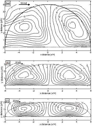
In both structural and environmental wind engineering, the vertical variation of wind direction is important as it impacts both the torsional response of the high rise building and the pedestrian level wind environment. In order to systematically investigate the vertical variation of wind directions (i.e., the so called ‘twist effect’ effect‟) induced by hills with idealized geometries, a series of wind tunnel tests was conducted The length to width aspect ratios of the hill models were 1/3, 1/2, 1, 2 and 3, and the measurements of both wind speeds and directions were taken on a three dimensional grid system. From the wind tunnel tests, it has been found that the direction changes and most prominent at the half height of the hill. On the other hand, the characteristic length of the direction change , has been found to increase when moving from the windward zone into the wake. Based on the wind tunnel measurements, a descriptive model is proposed to calculate both the horizontal and vertical variations of wind directions. Preliminarily validated against the wind tunnel measurements, the proposed model has been found to be acceptable to describe the direction changes induced by an idealized hill with an aspect ratio close to 1. For the hills with aspect ratios less than 1, while the description of the vertical variation is still valid, the horizontal description proposed by the model has been found unfit.
Read more
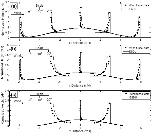
CFD simulation of wind direction field under the influence of topography
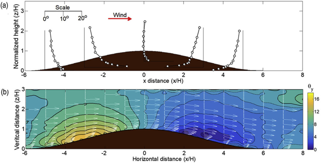
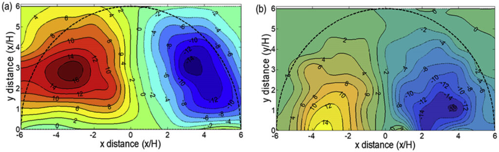
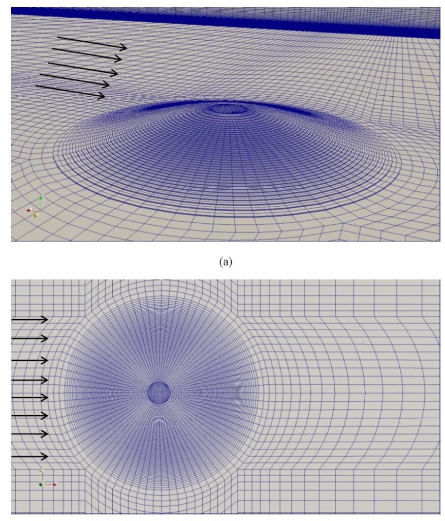
Though hilly topography influences both wind speeds and directions aloft, only the influence on wind speeds, i.e. the speed up effect, has been thoroughly investigated. Due to the importance of a model showing the spatial variations of wind directions above hilly terrains, it is worthwhile to systematically assess the applicability and limitations o f the model describing the influence of hilly topographies on wind directions . Based on wind tunnel test results, a model, which describes the horizontal and vertical variations of the wind directions separately, has been proposed in a companion paper. CFD (Computational Fluid Dynamics) techniques were employed in the present paper to evaluate the applicability of the proposed model. From the investigation, it has been found that the model is acceptable for describing the vertical variation of wind directions by a shallow hill whose primary to secondary axis ratio (aspect ratio) is larger than 1. When the overall hill slope exceeds 20°, the proposed model should be used with caution. When the aspect ratio is less than 1, the proposed model is less accurate i n predicting the spatial variation of wind directions in the wake zone in a separated flow. In addition, it has been found that local slope of a hill has significant impact on the applicability of the proposed model. Specifically, the proposed model is only applicable when local slope of a hill varies gradually from 0 (at the hill foot) to the maximum value (at the mid slope point) and then to 0 (at the hill top).
Read more
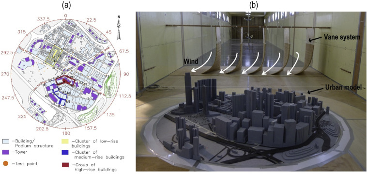
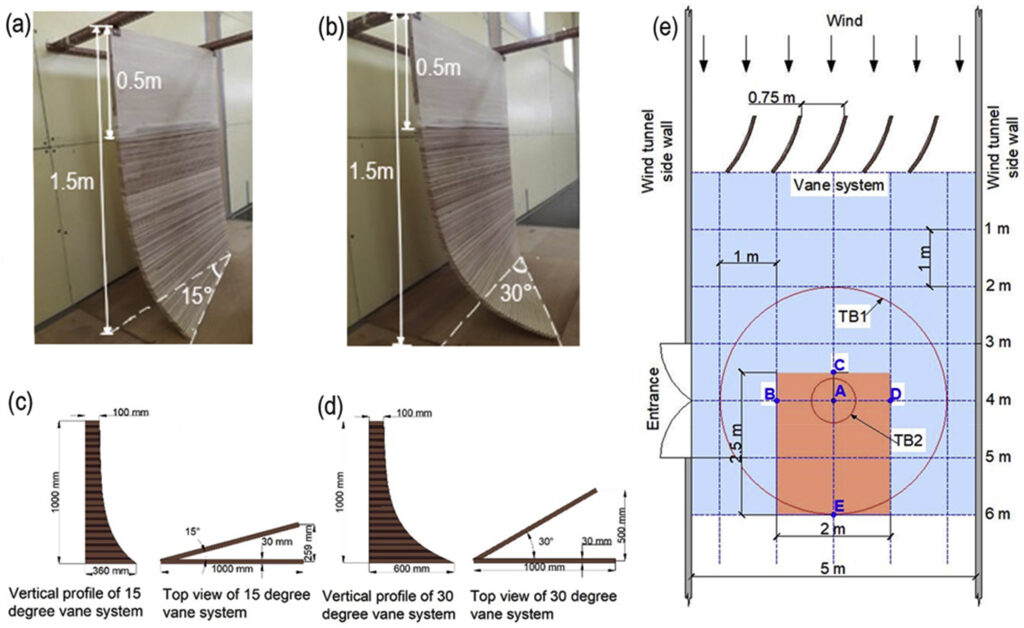
Simulation of twisted wind flows in a boundary layer wind tunnel for pedestrian-level wind tunnel tests
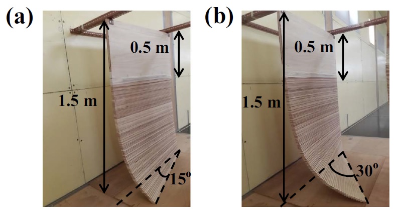
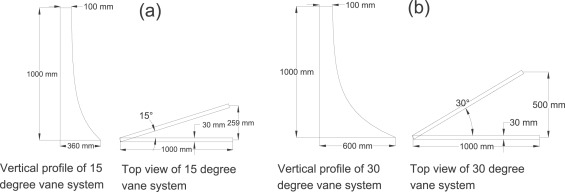
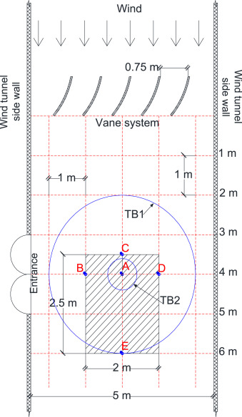
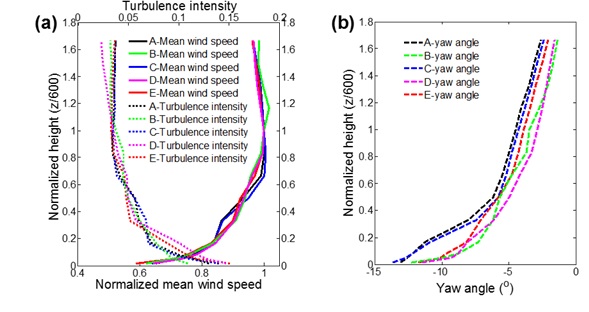
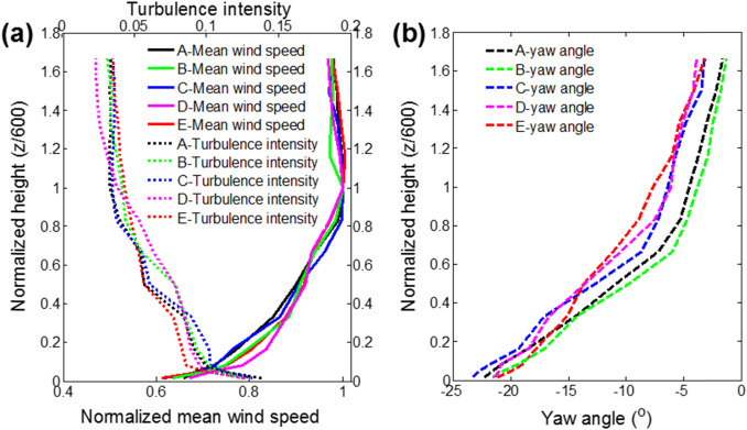
Topography-induced twisted wind flows are frequently observed in Hong Kong due to the abundance existence of mountains. Observed twisted wind profiles are with larger wind twist angles and are confined to the lower 500 m of the atmosphere, thus may impose significant effects on both structures and near-ground wind conditions. In order to investigate the influences of twisted wind flows on the pedestrian-level wind environment, two twisted wind profiles were simulated in a boundary layer wind tunnel by using 1.5 m tall wooden vanes. The maximum guide angles of vanes were 15° and 30° at the ground level to represent two nominal yaw angles of ‘high’ and ‘extreme’ twisted wind flows. Simulated twisted wind profiles followed the power-law profile and have acceptable longitudinal and lateral turbulence power spectra similar to conventional wind flows. The yaw angle profiles were exponentially decayed with the height but had smaller maximum yaw angles than of the guide vanes. The evaluation of wind conditions near an isolated building and a row of buildings in twisted wind flows has displayed substantially modified flow features such as asymmetric wind speed distributions about the building centre line and reduced wind speeds in the passages between buildings.
Read more
Integrating topography-modified wind flows into structural and environmental wind engineering applications
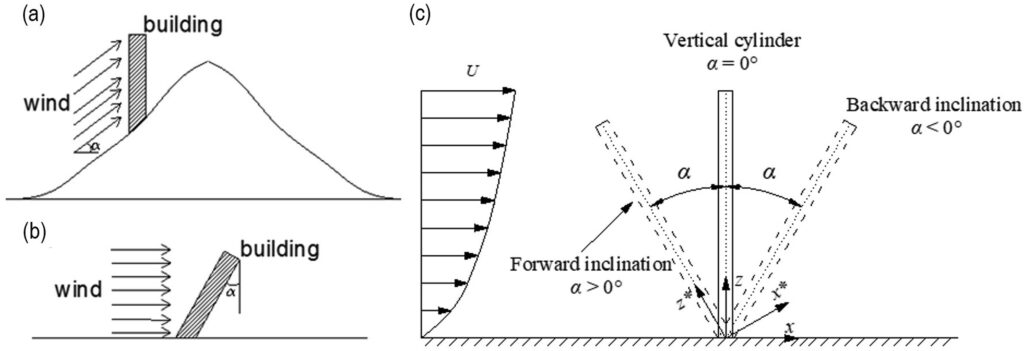
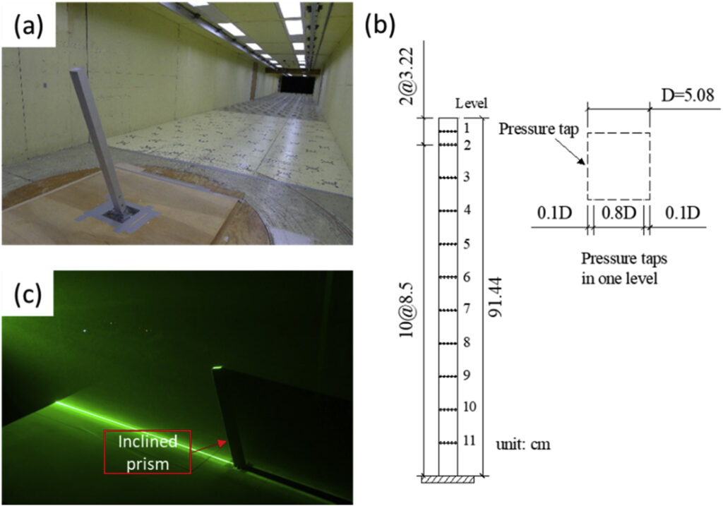
Topographical features alter the trajectory of wind on the horizontal and vertical planes by creating yaw and pitch angles of wind. Near mountains, topography-induced pitch and yaw angles are confined to the lower part of the atmospheric boundary layer and have considerable magnitudes, thus they should be taken into consideration in wind engineering applications. In this study, a series of wind tunnel tests and CFD simulations are conducted to investigate how wind flows with pitch and yaw angels affect the wind loading of structures and the wind environment in built-up areas. Wind flows with yaw angles are found to create asymmetric pedestrian-level wind environments with large low-wind areas. These results can be replicated using conventional wind flows with a novel technique called the equivalent wind incidence angle method. Wind flows with small positive pitch angles exaggerate the displacements and wind loadings of structures, while negative pitch angles are advantageous for the aerodynamic performance of structures. The differential structural aerodynamics performances are attributable to differences in downwash and upwash flows, and curvature of the shear layers at the top and bottom of a structure subjected to wind flows with positive and negative pitch angles.
Read more